



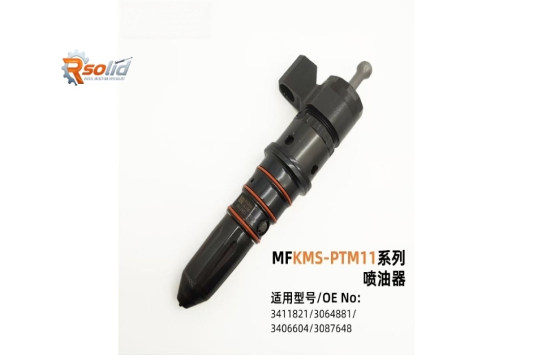
Cummins 3411821 / MFKMS-PTM11 Diesel Injector – Structure, Applications, Faults & Maintenance Guide
Cummins 3411821 / MFKMS-PTM11 Diesel Injector: In-Depth Review for ISM11 & QSM11 Engines
The 3411821 injector (also marketed under the cross-reference MFKMS-PTM11) is a high-performance fuel injection unit specifically engineered for Cummins ISM11 and QSM11 heavy-duty diesel engines. Whether you operate a commercial truck, construction equipment, or a marine vessel, this injector plays a critical role in combustion efficiency, power output, and emissions control.
In this comprehensive guide, we break down the injector’s structural design, typical application fields, most common failure modes, and proven maintenance/installation best practices – all optimized to help you reduce downtime and lower total cost of ownership.
1. Product Structure & Design Features
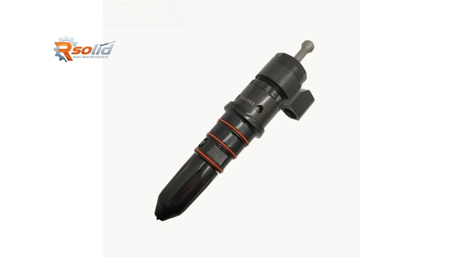
The 3411821 / MFKMS-PTM11 is a hydraulically actuated, electronically controlled unit injector (HEUI) – though strictly speaking, the ISM/QSM platforms use a high-pressure common-rail (HPCR) or mechanically actuated electronic unit injector (MEUI) depending on the generation. For the ISM11 and QSM11 (both based on the Cummins M11 platform), the injector is a MEUI (Mechanically Actuated Electronic Unit Injector) with the following structural highlights:
Body Material: High-strength alloy steel with anti-corrosion coating, designed to withstand in-cylinder pressures exceeding 2,000 bar.
Plunger & Barrel Assembly: Precision-ground matched pairs that ensure consistent fuel metering. The plunger is driven by the engine camshaft via a rocker arm, creating the high injection pressure.
Solenoid Valve (Actuator): A high-speed solenoid that controls the start and end of injection. The ECM (Engine Control Module) sends pulse-width modulated signals to precisely time fuel delivery.
Nozzle Assembly: Multi-hole sac-type or VCO (Valve Closed Orifice) nozzle with hardened tips to resist erosion and coking. Typical hole count: 8–10, with optimized spray angles for the ISM/QSM combustion bowl.
Fuel Return & Leak-off Ports: Internal passages that recirculate excess fuel for cooling and lubrication, plus a spill port that regulates injection pressure.
O-ring Seals: Viton® or PTFE seals at the top and bottom to prevent fuel leakage into the crankcase or combustion chamber.
Electrical Connector: Deutz-style two-pin connector, fully sealed against moisture and vibration.
Key dimensional specification: The injector has a specific protrusion height (distance from the cylinder head face to the nozzle tip) that must be set using shims – critical for correct spray penetration and piston bowl targeting.
2. Common Application Equipment
The 3411821 / MFKMS-PTM11 injector is OEM and aftermarket replacement for Cummins ISM11 (11-liter, 310–440 hp) and QSM11 (11-liter, 335–500 hp) engines. These powerplants are found in a wide variety of demanding applications:
| Equipment Category | Typical Models |
|---|---|
| Heavy-Duty Trucks | Kenworth T800/W900, Peterbilt 379/387, Freightliner Columbia/Cascadia, International 9900i (with ISM) |
| Construction Machinery | Caterpillar excavators (using Cummins re-power), Komatsu PC-series, Volvo EC-series, Terex haulers |
| Mining & Quarry | Haul trucks (e.g., Euclid, Hitachi), wheel loaders, drill rigs |
| Marine Propulsion | Commercial fishing vessels, tugboats, auxiliary gensets, pleasure craft with QSM11 marine ratings |
| Agricultural | Large tractors, self-propelled sprayers, combine harvesters (AGCO, Case IH with Cummins power) |
| Industrial & Stationary | Gensets (prime/standby), water pumps, oilfield fracturing pumps, compressor drives |
The injector is interchangeable with earlier part numbers (e.g., 3408321, 3411786) but is the latest supersession – offering improved spray pattern and durability for EPA Tier 2/Tier 3 and Stage II/III emissions compliance.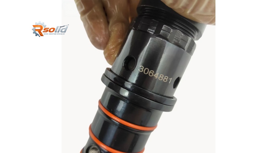
3. Common Failures & Symptoms
Despite robust construction, the 3411821 injector is subject to wear and contamination. Early detection saves expensive engine damage. Here are the most frequent failure modes:
3.1 Solenoid Coil Failure
Cause: Thermal cycling, voltage spikes, or moisture ingress.
Symptoms: Engine misfire, rough idle, loss of power, DTC codes (e.g., 113, 124, 166 – injection timing/actuator circuit).
Diagnosis: Measure coil resistance (typically 0.5–1.5 Ω at 20°C); out-of-range = replace.
3.2 Sticking / Binding Plunger
Cause: Fuel contamination (water, dirt, abrasive particles), poor fuel filtration, or degraded fuel with low lubricity.
Symptoms: Erratic fuel delivery, knocking noise, white/black smoke, hard starting, surge at steady speed.
Progression: If ignored, can seize the plunger, causing camshaft/rocker arm damage.
3.3 Nozzle Coking / Orifice Erosion
Cause: High combustion temperatures, poor fuel quality, or incorrect injection timing.
Symptoms: Reduced fuel economy, increased smoke (especially black), failed emissions test, and power loss under load.
Visual: Carbon buildup on the tip; eroded holes cause unequal spray pattern.
3.4 Leaking O-ring Seals
Cause: Ageing, heat, improper installation (nicked or twisted seals).
Symptoms: Fuel in engine oil (rising oil level), fuel odor, hard starting, and possible crankcase dilution leading to bearing wear.
3.5 Internal Leakage (Spill Valve Wear)
Cause: Normal wear over 5,000+ hours, or abrasive particles scoring the valve seat.
Symptoms: Lower rail pressure (in common-rail variants) or reduced injection volume – results in low power and high EGT (exhaust gas temperature).
3.6 Electrical Connection Corrosion
Cause: Moisture/salt in marine or road-salt environments.
Symptoms: Intermittent injector cutout, engine stumble, diagnostic trouble codes.
4. Maintenance & Installation Best Practices
Proper handling and scheduled maintenance are essential to get the full service life (typically 8,000–10,000 hours for highway use, 5,000–8,000 for heavy off-road).
4.1 Preventive Maintenance Schedule
Fuel Filtration: Replace primary and secondary fuel filters every 500 hours or per OEM specs. Use 10-micron (or finer) absolute filters. Install a fuel/water separator if not already equipped.
Fuel Quality: Use ASTM D975 Grade No. 2-D or equivalent, with minimum cetane number 45. Add lubricity enhancer if using ultra-low sulfur diesel (ULSD).
Injector Balance Test: Run the Cummins INSITE™ software to perform a cylinder performance test at each major service (1,000 hours). Compare injector trim codes – if deviation exceeds ±3%, investigate.
Valve Lash Adjustment: Since the injector is cam-driven, maintain proper rocker arm clearance (intake/exhaust and injector adjuster). Incorrect lash alters injection timing and can cause mechanical overstress.
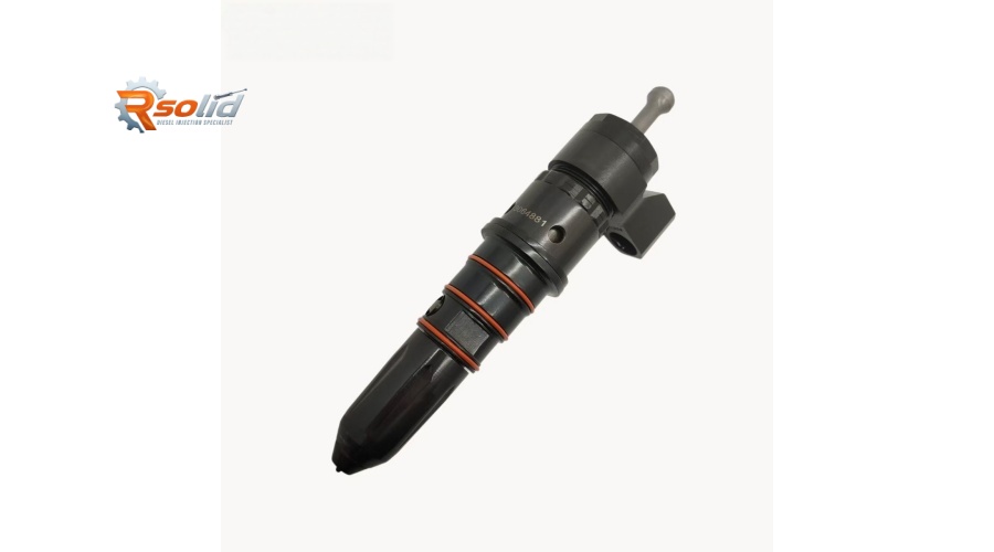
4.2 Installation Step-by-Step (Critical DOs & DON’Ts)
| Step | Action | Key Point |
|---|---|---|
| 1 | Clean the injector bore in the cylinder head thoroughly – use a bore brush and vacuum to remove carbon and debris. | Contamination is the #1 cause of premature failure. |
| 2 | Lubricate the new O-rings with clean engine oil or recommended assembly lube – do not use grease or silicone. | Grease can block fuel passages and degrade seals. |
| 3 | Insert the injector carefully – do not force it. Rotate gently to align the hold-down clamp. | Forcing can damage the nozzle tip. |
| 4 | Install the correct injector protrusion shim (calculated from the cylinder head recession measurement). Refer to Cummins Service Manual. | Incorrect protrusion causes piston impingement or poor combustion. |
| 5 | Torque the hold-down bolt to specification – typically 65–75 N·m (48–55 lb-ft) for M8 bolt; but confirm for your engine serial number. | Over-torque distorts the injector body; under-torque causes leakage and movement. |
| 6 | Connect the electrical harness – ensure the clip is fully latched and the wire routing avoids hot surfaces or moving parts. | |
| 7 | After installation, prime the fuel system (manually or with the lift pump) and bleed air. Crank engine without starting for 10 seconds twice to fill injectors. | |
| 8 | Start engine and check for leaks – run at idle for 5 minutes, then perform a cylinder cut-out test via INSITE to verify each injector contributes equally. | |
| 9 | Re-torque the hold-down bolt after the first heat cycle (warm engine) – this compensates for thermal expansion. |
4.3 Special Notes for Marine Applications
Use marine-grade O-rings (if available) with enhanced salt-water resistance.
Install a secondary fuel/water coalescing filter to handle condensation in fuel tanks.
Flush the fuel rail with clean fuel if you suspect water ingress before installing new injectors.
4.4 Remanufactured vs. New
The MFKMS-PTM11 is widely available as a genuine Cummins reman (Interact™) or aftermarket new. Reman units are flow-tested and calibrated – a cost-effective choice for fleet owners. However, always verify that the reman includes a new solenoid, nozzle, and plunger/barrel assembly – not just cleaning and resealing.
5. Troubleshooting Quick Reference
| Symptom | Likely Injector Issue | Action |
|---|---|---|
| Hard start / long crank | Low injection pressure (plunger wear or spill valve leak) | Perform leak-off test; replace injector if leak-off exceeds 30 mL/min. |
| White smoke at idle | Retarded timing or poor atomization (nozzle coking) | Clean or replace nozzle; check solenoid response. |
| Black smoke under load | Over-fueling (sticking plunger) or incorrect trim code | Run injector calibration; replace if trim cannot be adjusted. |
| Rough running / misfire | Electrical or mechanical failure in one cylinder | Swap injectors between cylinders; if fault follows, replace that injector. |
| Fuel in oil | Leaking O-rings or cracked injector body | Inspect seals; replace injector and change oil/filter. |